Title here
Summary here
Topological data analysis (TDA) typically shines on data with shape and structure. In nature, such patterns arise constantly. Proteins have cavities and tunnels, galaxies form filaments, and porous materials are characterized by a network of interconnected channels. Although these kinds of structures do contain some amount of randomness (i.e., a stochastic process that underlies the formation), it seems that Nature prefers shape over uniformity. Only through shape can the intricate structures that dictate our biology form.
But shape doesn’t only arise in our own chemistry; it also appears in one of humanity’s most complex creations: semiconductor manufacturing. In this field, electronic circuits are built directly onto a thin slice of crystalline silicon called a wafer. In this process, the wafer is coated with a light-sensitive chemical and is then exposed to light through a patterned mask. This transfers an incredibly fine circuit design onto the surface. These are essentials of a process called lithography.
One of the biggest challenges in lithography is defects. Defects appear on a chip-by-chip basis across the wafer, together forming a defect pattern. As a topologist, I see patterns as a sign of structure, and where there is structure, topology is the right tool to invoke. The ability to classify these defect patterns and to connect them to their corresponding root causes has real value. This is because wafers with similar defect distributions may point to a common problem in a specific process step.
In a paper by Seungchan Ko and Dowan Koo [1], the authors used tools from topology for defect pattern classification. Crucially, the authors note that convolutional neural networks (CNNs) have drawbacks for pattern classification. Among the drawbacks, they mention that:
The last point matters for the following reason: defects occur as rare events. Many machine learning models implicitly assume that the data being fed into the system is relatively balanced. But when the model is being trained on skewed data, it tends to optimize the most common cases. As a result, the model can achieve high accuracy while predicting the absence of any defect almost every time. It thus misses the rare defects that actually matter. Worse, defective patterns stem from different causes in the manufacturing process. Hence, the dataset is unbalanced from the start.
To overcome these obstacles, it could be advantageous to represent the initial data in a completely different way. In [1], the authors suggest extracting a topological feature from the given defect pattern on a wafer, representing it as a so-called persistence image, and only then use these PIs as inputs to neural networks for classification.
In this post, I will assume that you know how to construct a persistence diagram (PD) from a multiset of points in . Recall that in a PD, each point is given by a pair standing for (birth, death). The authors define a map . Any point will now be of the form . This means that points close to the horizontal axis are short-lived noise, while points higher up are more robust or persistent.
This is just a coordinate transformation; nothing has happened yet to make machine interpretability easier. The authors then turn the point set into a continuous surface. Instead of one “spike” per point, the authors blur the points using Gaussians. But not each Gaussian should be as tall: persistence should be emphasized, while noise should be close to flat. This is where a weighting function comes in. The chosen is zero on the horizontal axis and grows with persistence. Assuming to be a Gaussian bump for a point , the persistence surface is given by the weighted sum
This produces a smooth surface, but to use it in a machine learning model, the surface must be discretized. The authors do this using integration.
The result is a persistence image, which is then represented as a vector, used as the input of a machine learning model. Figure 1 illustrates the entire pipeline, starting with the original image from [1].
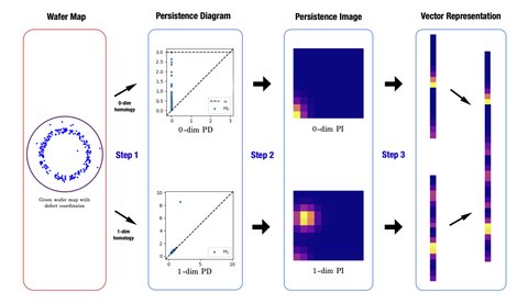
To test the proposed method’s performance, the authors used simulated datasets based on real data from experiments in other research papers. The authors classify defects with 99% accuracy, improving over CNN-based models that achieved 93.8% accuracy. While this difference is modest, the authors point out that their model outperforms in a real manufacturing process because their model:
Machine learning heavily relies on the data you feed it. By using techniques from topology before training, much of the unnecessary data is removed from the system, so that the model can be trained on the type of data that really matters. This reduces time and improves efficiency. Topology saves the day!
A novel approach for wafer defect pattern classification based on topological data analysis,Expert Systems with Applications, vol. 231, p. 120765, 2023. doi:10.1016/j.eswa.2023.120765